Hello,
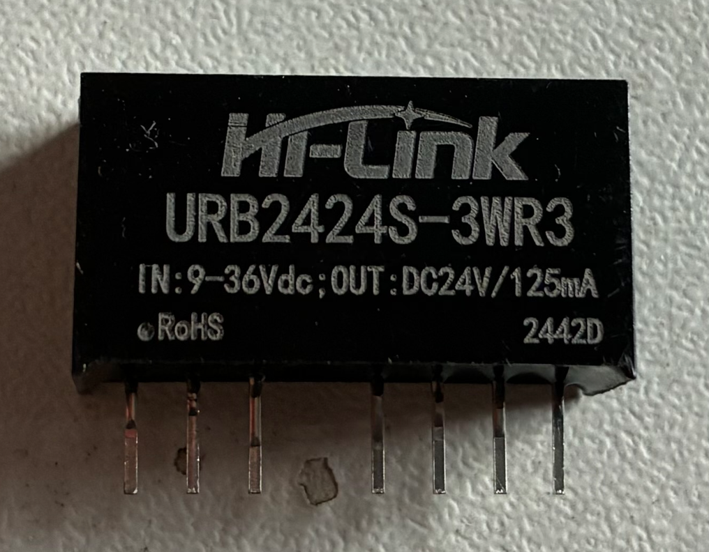
I am using the URB2424S-3WR3 DC/DC converter module in my design and I have observed a discrepancy between the datasheet description and the actual behavior of the device.
According to the datasheet:
“When floating or high resistance, the module outputs normally; when connected to a high level (relative to the input ground), the module is turned off.”
However, in my measurements the behavior is different.
Test conditions
Input voltage: 24 V
CTRL pin connected through a 390 Ω resistor to a microcontroller GPIO
Common input ground used
GPIO states tested: HIGH, LOW, and High-Z
Observed behavior
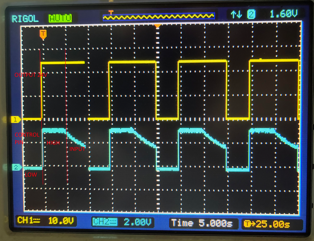
When CTRL is pulled LOW through ~390 Ω, a current of approximately 70 uA flows from the module into the CTRL pin, and the module turns OFF
When CTRL is HIGH or High-Z, no significant current flows and the module remains ON
This indicates that the module turns off when current is sunk from the CTRL pin, rather than when a high logic level is applied.
Concern
This behavior appears opposite to the description in the datasheet. It seems that the CTRL pin is current-driven (possibly diode/opto-coupler based) and not a standard logic-level input.
Question
Could you please clarify:
Is the CTRL pin behavior current-controlled rather than voltage-controlled?
Is the correct OFF condition achieved by sinking current (pulling CTRL low through a resistor)?
Could this discrepancy be due to a revised internal design or different hardware revision?
Is it possible that the modules purchased from third-party suppliers (e.g. AliExpress) are inconsistent with the official specification, or is this behavior expected?